Construc Camshaft (talk | contribs) |
mNo edit summary Tag: Visual edit |
||
| (24 intermediate revisions by 3 users not shown) | |||
| Line 1: | Line 1: | ||
| − | == |
+ | == Overview == |
| + | A fixture is a collection of files, for which a <code>cpp</code> file serves as the parent file. All the settings for a fixture are inside this <code>cpp</code> file. |
||
| − | * Fixtures are a Blueprint class, A_Fixture is the base class. |
||
| − | * Fixtures are comprised of up to 4 Sub-meshes ([[#UV Mesh|UV Mesh]], [[#Conforming Mesh|Conforming Mesh]], [[#Skinned Mesh|Skinned Mesh]], and [[#Additional Mesh|Additional Mesh]]). |
||
| − | * All or none of these are required: |
||
| − | **UV Mesh (the silhouette of the cut out) |
||
| − | **Conforming mesh (e.g. Grilles, or the front headlight glass) |
||
| − | **Addditional Mesh (Things like Wing Mirrors) |
||
| − | **Skinned Mesh (Headlight Internals) |
||
| − | * A Fixture Category |
||
| − | * Snap to Centre Strength |
||
| − | * Lock to Cardinal (should it always face forwards, backwards, etc. Rather than face in the direction of the car body normal.) |
||
| − | * Needs [[Material Slots]] setup correctly |
||
| − | * Needs [[Preview Thumbnails]] |
||
| + | Fixtures are comprised of up to 4 optional sub-meshes (a [[#UV Mesh|UV mesh]], [[#Conforming Mesh|conforming mesh]], [[#Skinned Mesh|skinned mesh]], and [[#Additional Mesh|additional mesh]]) depending on the type of fixture: |
||
| − | == The Fixture Blueprint and its Components == |
||
| − | A |
+ | *A '''UV mesh''' is the silhouette of the cutout hole that a fixture makes in a car body. |
| + | *A '''conforming mesh''' (e.g. grilles, outer light glass, or body moulding) will deform to the shape of the body. |
||
| + | *A '''skinned mesh''' (e.g. light internals) will maintain its relative internal shapes, but will conform roughly to the shape of the body. |
||
| + | *An '''addditional mesh''' (e.g. mirrors) will retain its shape no matter where it is placed on the body. |
||
| + | |||
| + | Fixtures need [[Material Slots|material slots]] set up correctly to look as intended, and [[Preview Thumbnails|preview thumbnails]] to appear in-game. |
||
| + | |||
| + | ==Performance considerations== |
||
| + | The performance of fixtures (and bodies) in UE4 is a constant discussion of balance. |
||
| + | |||
| + | There is a performance impact to poly count with fixtures in that a ray is cast to the body for every vertex; the more vertices there are in a mesh, the longer it'll take to conform to the body. This is why you'll see more detailed fixtures sit there for a few seconds before conforming to the car. |
||
| + | |||
| + | This is doubly so for fixtures that cut into the body—a UV mesh's vertices are raycast to the car on every frame while you're dragging the fixture around. UV meshes impact performance significantly with a higher poly count; try to keep UV meshes as low-poly as possible. |
||
| + | |||
| + | === For optimal performance: === |
||
| + | |||
| + | *Keep UV meshes lower than 100 triangles. With between 100 and 150 triangles, the fixture may lag when being dragged around; any higher and it will lag too much to use properly. |
||
| + | *Try to keep conforming meshes lower than 5,000 triangles. Higher-resolution meshes take longer than usual to conform to the car once they are placed. |
||
| + | |||
| + | == Fixture blueprints == |
||
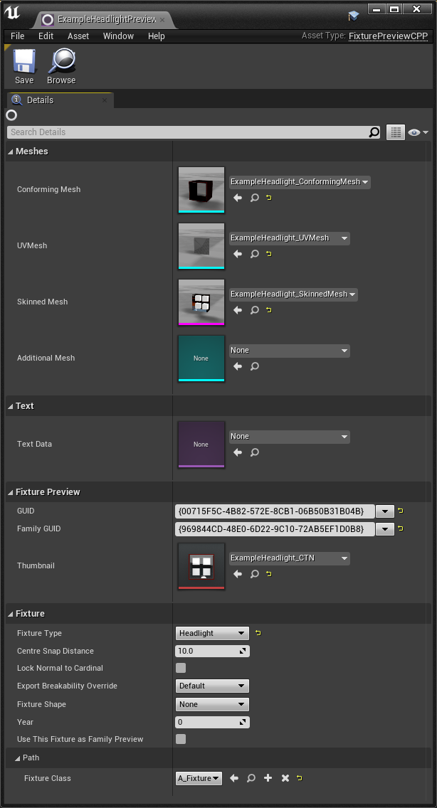
| + | [[File:FixtureExampleSettings.png|alt=|right|frameless|700x700px]]A Fixture is composed of a Blueprint that contains the fixture settings and sub-meshes. |
||
=== Fixture Settings === |
=== Fixture Settings === |
||
| + | Meshes (more on these later): |
||
| − | [[File:FixtureExampleSettings.png|none|thumb]] |
||
| + | |||
| + | *'''Conforming Mesh''' - Defines the ''Static Mesh'' sub-mesh used by this fixture. |
||
| + | * '''UV Mesh''' - Defines the ''UV Mesh'' sub-mesh used by this fixture. |
||
| + | *'''Skinned Mesh''' - Defines the ''Skinned Mesh'' sub-mesh used by this fixture. |
||
| + | *'''Additional Mesh''' - Defines the ''Additional Mesh'' sub-mesh used by this fixture.'''<nowiki/><nowiki/><nowiki/><nowiki/>''' |
||
| + | |||
| + | Text: |
||
| + | |||
| + | * '''Text Data''' - Currently not used. |
||
| + | |||
| + | Fixture Preview: |
||
| + | |||
| + | *'''GUID''' - Unique identifier for this fixture. |
||
| + | *'''Family GUID''' - Identifier for this fixture family. This should be unique to every other family GUID, and identical to every other variant of this fixture. |
||
| + | |||
| + | Fixture: |
||
| + | *'''Fixture Type''' - What category this fixture should be in (e.g. headlight, aerial, grille, etc). |
||
| − | Fixture settings are grouped in to two categories: '''Editable''', and '''Fixture'''. |
||
| − | * |
+ | *'''Centre Snap Distance''' - Defines at what distance, in cm, the fixture will snap to the centre line of the car (10 by default). |
| + | *'''Lock Normal to Cardinal<nowiki/>'''- Determines whether the fixtu'''<nowiki/>'''re will conform to'''<nowiki/>''' one of the five cardinal directions in 3d space (forwards, backwards, left, right, or upwards) by default. A non-cardinal-locked fixture will simply face in the direction of the surface on which it '''<nowiki/>'''is placed. Cardinal locking is useful for fixtures such as lights and mirrors, since it ensures that they don't face in (or conform to) odd directions. |
||
| − | * '''Fixture''' settings are for where the fixture is located in the Automation UI. |
||
| + | *'''Export Breakability Override''' - Certain categories of fixtures can break off when damaged in BeamNG.drive. This setting lets you force a fixture to be breakable or unbreakable. |
||
| + | *'''Fixture Shape''' - Used to filter fixtures by rectangular, round, or complex shapes. Mostly used for lights. |
||
| + | *'''Year''' - Used to filter fixtures by year. Useful for era-specific fixtures, such as sealed beam headlights. |
||
| + | *'''Use This Fixture as Family Preview''' - if you have many variants of a fixture, enabling this setting for one variant will make it the one that shows up in the main fixture menu (overriding the first fixture as per alphabetical order). |
||
| + | Path: |
||
| − | ==== Editable settings ==== |
||
| − | * '''Centre Snap Distance''' - Defines at what distance the fixture will snap to the centre line of the car (default 10cm) |
||
| − | * '''Conforming Mesh''' - Defines the ''Static Mesh'' sub-mesh used by this fixture |
||
| − | * '''UVMesh''' - Defines the ''UVMesh'' sub-mesh used by this fixture |
||
| − | * '''Skinned Mesh''' - Defines the ''Skinned Mesh'' sub-mesh used by this fixture |
||
| − | * '''Additional Mesh''' - Defines the ''Additional Mesh'' sub-mesh used by this fixture |
||
| − | * '''Lock Normal to Cardinal'<nowiki/>'' - When the fixture is set to ''<nowiki/>'Lock to Cardinal'<nowiki/>'': all the vertices of the ''Conforming Mesh,'' all the bones of the ''Skinned Mesh'' , and the ''Additional Mesh'', will conform backwards in to the car at the closest 90° angle. When the fixture is not set to ''<nowiki/>'Lock to Cardinal''': all the vertices of the ''Conforming Mesh,'' all the bones of the ''Skinned Mesh'', and the ''Additional Mesh'', will conform inwards from the centre of the fixture. |
||
| + | * '''Fixture Class''' - Set this to <code>A_Fixture</code> to ensure that the fixture works as intended in-game. |
||
| − | ==== Fixture settings ==== |
||
| − | * '''Fixture GUID''' - Unique identifier for this fixture. |
||
| − | * '''Family GUID''' - Identifier for this fixture family. Should be unique to every other family GUID, and identical to every other variant of this fixture |
||
| − | * '''Fixture Type''' - What category this fixture should be in (ie: headlight, aerial, grille, etc...) |
||
| − | * '''M Ghost Material''' - Defines the material to use when the fixture cannot be placed where the player is attempting to place it. This setting shouldn't change from its default 'FixtureError' material <s>unless you really want to change it.</s> |
||
=== Fixture Sub-Meshes === |
=== Fixture Sub-Meshes === |
||
==== UV Mesh ==== |
==== UV Mesh ==== |
||
| − | + | The ''UV Mesh'' (imported as a '''Static Mesh''' in UE4) is a flat silhouette that tells the fixture to cut a hole into the car body. You will only need vertices along the outside edges of the UV mesh, and an UV mesh is only required if your fixture intends to cut into the car. |
|
==== Conforming Mesh ==== |
==== Conforming Mesh ==== |
||
| − | + | The ''Conforming Mesh'' (imported as a '''Static Mesh''' in UE4) is a mesh where each vertex is deformed to match the surface of the car body. It is also a required mesh if the fixture has a UV mesh, as the conforming mesh is used to cover the jagged edge of the hole created by the UV mesh. A conforming mesh that could logically be placed on top of other fixtures should also have its outside edges extend beneath the body; the default distance for this extrusion is slightly farther than 10 cm. |
|
==== Skinned Mesh ==== |
==== Skinned Mesh ==== |
||
| − | + | The ''Skinned Mesh'' (imported as a '''Skeletal Mesh''' in UE4) is used when you have parts of a fixture that should conform to the rough shape of the car, but also retain the dimensions and ratios of any individual components. A skinned mesh will have a bone for each element that is parented to a root bone. |
|
| + | |||
| + | All vertices of the skinned mesh that are within 1.5 mm of the car body surface will conform to the car as if they were part of a conforming mesh. Because of this, there may be a small gap of at least 1 mm between the edge of the skinned mesh and the car body. To cover up this gap, a conforming mesh is used to connect the edge of the skinned mesh with the car body. |
||
==== Additional Mesh ==== |
==== Additional Mesh ==== |
||
| − | + | The ''Additional Mesh'' (imported as a '''Static Mesh''' in UE4) does not deform in any way and will remain in place relative to the location of the fixture. An additional mesh has no skin or bones, and no part of it will deform to the shape of the car. Examples of additional meshes are exhaust tips and wing mirrors. |
|
| − | == |
+ | == Modelling a fixture == |
| − | + | '''''Note:''' This how-to assumes a general understanding of polygonal 3D modelling software. Any 3D modelling package will do, as no custom scripts are required to author fixture meshes.'' |
|
| + | Hard Rooster has created a full video series for fixture modding in Blender. |
||
| + | {{#ev:youtube|zDKdTI0v4DE}} |
||
| + | The full series can be found [https://www.youtube.com/playlist?list=PLb7obMX2SCf0V3dlxfOHnB9eKtP3c_KEZ here.] |
||
=== Fixture Orientation === |
=== Fixture Orientation === |
||
| + | Fixtures are oriented in the following manner in a 3D modelling program. Note how the negative Y axis faces forwards. |
||
| − | Fixtures are oriented in the following manner in the 3D authoring package:[[File:Fixture Orientation Example.jpg|alt=Fixtures come out of the car towards the -Y axis. -X is left, +X is right, and +Z is up, -Z is down|none|thumb|Fixtures come out of the car towards the -Y axis. -X is left, +X is right, and +Z is up, -Z is down|link=https://automation.gamepedia.com/File:Fixture_Orientation_Example.jpg]] |
||
| + | [[File:Fixture_Orientation_Example.jpg|link=https://automation.gamepedia.com/File:Fixture_Orientation_Example.jpg|alt=Fixture Orientation Example|none|thumb|360x360px|Fixtures come out of the car towards the -Y axis. -X is left, +X is right, +Z is up, and -Z is down.]] |
||
=== Fixture Y-Axis Thresholds === |
=== Fixture Y-Axis Thresholds === |
||
| − | There are |
+ | There are 2 important values to take in to note for fixture sub-meshes. |
| − | * A |
+ | * A skinned mesh will have some of its vertices conform to the car as if it were a conforming mesh, but only if those vertices are within '''''1.5 mm''''' from Y=0. A vertex with a Y axis value of 1.5 mm will conform to the car as if it were part of a conforming mesh, and a vertex with a Y axis value of 2.0 mm will not. |
| + | * The outer edges of most conforming meshes (and inner edges of things with holes in them, like open grilles) usually sit '''''10.114 cm''''' below the surface (that's a Y-axis value of 10.114cm). This stops fixtures from appearing to 'float' when put on top of other fixtures that cut into cars and leave holes, such as grilles. |
||
| − | * Grilles go in to the car 4.301cm (that's a Y-axis value of 4.301cm). Any fixture (like a headlight) that could be feasably placed on top of a grille fixture should have all of its important mesh structure between this point and the front of the fixture. |
||
| + | |||
| − | * The outer edges of most ''Conforming Meshes'' (and inner edges of things with holes in them, like open grilles) go in to the car 10.114cm (that's a Y-axis value of 10.114cm). This stops fixtures from appearing to 'float' when put on top of other fixtures that cut in to cars and leave a gap, such as grilles. |
||
| − | Here's a visual representation of these values: |
||
| − | [[File:Fixture y-axis values.gif|alt=Note the Conforming Mesh (White) extends out of the car (pink, lowermost) and connects with the Skinned Mesh, as well as having its outside edges go as far back as the rest of the open grilles etc (pink, topmost).. and the Skinned Mesh (Blue) extends only as far back as the grille plane (middle pink), with the headlights being between the grille plane (middle pink) and front of the car fixture (bottom pink)|none|thumb|Note the ''Conforming Mesh'' (White) extends out of the car (pink, lowermost) and connects with the ''Skinned Mesh'', as well as having its outside edges go as far back as the rest of the open grilles etc (pink, topmost).. and the ''Skinned Mesh'' (Blue) extends only as far back as the grille plane (middle pink), with the headlights being between the grille plane (middle pink) and front of the car fixture (bottom pink)]] |
||
It's a bit confusing at first, but following these rules will ensure your fixture works correctly. |
It's a bit confusing at first, but following these rules will ensure your fixture works correctly. |
||
| − | === Deciding |
+ | === Deciding What Sub-Meshes You'll Need === |
Fixtures have a fairly convoluted list of things that ''are'' or ''are not'' needed, depending on what is in the fixture. |
Fixtures have a fairly convoluted list of things that ''are'' or ''are not'' needed, depending on what is in the fixture. |
||
| − | *If you have |
+ | *If you have a [[Fixture Mods#UV Mesh|UV mesh]], you need a [[Fixture Mods#Conforming Mesh|conforming mesh]] to cover the hole. |
| − | *If you have a |
+ | *If you have a conforming mesh, it isn't required to have anything else unless said Conforming Mesh has parts that go below the car body mesh (in which case you'll need a UV Mesh to cut a hole out for it). |
| − | *If you have a [[Fixture Mods#Skinned Mesh| |
+ | *If you have a [[Fixture Mods#Skinned Mesh|skinned mesh]], you'll need a conforming mesh and a UV mesh, as a skinned mesh can only be inside the car. Therefore, a UV mesh is needed to cut out that hole, and a conforming mesh is needed to cover the edge of that hole. |
| − | *If you have an [[Fixture Mods#Additional Mesh| |
+ | *If you have an [[Fixture Mods#Additional Mesh|additional mesh]] positioned above the car body, nothing else is needed. If the additional mesh is obscured by the car body mesh, you'll need a UV mesh to cut out the hole for that (and by extension, a conforming mesh to line that hole). |
| − | For this example, We'll make the components for this headlight fixture:[[File:Fixture On Car Example.jpg|alt=|none|thumb|link=https://automation.gamepedia.com/File:Fixture_On_Car_Example.jpg]]We'll make a ''Conforming Mesh'', ''UV Mesh'', and a ''Skinned mesh'' with 4 bones. |
||
| + | For this example, we'll make the components for the headlight fixture below (a ''Conforming Mesh'', ''UV Mesh'', and a ''Skinned mesh'' with 4 bones). |
||
| − | === Creating the Sub-Meshes === |
||
| + | [[File:Fixture_On_Car_Example.jpg|link=https://automation.gamepedia.com/File:Fixture_On_Car_Example.jpg|frameless|360x360px]] |
||
| − | ==== Creating an UV Mesh ==== |
||
| − | [[File:UV Mesh Example.jpg|alt=An example UV Mesh|thumb|An example UV Mesh|300x300px|none|link=https://automation.gamepedia.com/File:UV_Mesh_Example.jpg]]The ''UV Mesh'' defines the [[wikipedia:Texel_(graphics)|texels]] of the car body that will be cut out by the fixture. Each vertex is used as a point of reference, and lines are drawn between them along the edges of the ''UV Mesh'' to define the final cut out shape on the car body. |
||
| + | === Creating the Sub-Meshes === |
||
| − | Note that if there are too few vertices, then the cutout shape will become distorted, as the vertices are projected on to the car texture then cut out, and the actual edges of the ''UV Mesh'' are not used, resulting in waviness in the final cutout shape. |
||
| + | ==== Creating a UV Mesh ==== |
||
| − | An ''UV Mesh'' should have vertices at regular intervals around the outside to determine the cutout shape of the fixture. Note that any vertices not on the outside edge are wasted and will only make the fixture slower to render. (''UV Meshes'' can be made in [[wikipedia:Annulus_(mathematics)|annulus]] shapes, like a doughnut). |
||
| + | The UV mesh defines the [[wikipedia:Texel_(graphics)|texels]] of the car body that will be cut out by the fixture. Each vertex is used as a point of reference, and lines are drawn between them along the edges of the UV mesh to define the final cutout shape. If there are too few vertices, the cutout shape will become distorted, since the vertices are projected onto the car texture before being cut out (with the actual edges of the UV mesh not being used), resulting in waviness between vertices in the cutout shape. This is more pronounced on larger fixtures, or fixtures that are stretched to several times their original size. |
||
| + | A UV mesh should have vertices at regular intervals around the outside to determine the cutout shape of the fixture. Any vertices that aren't on an edge are irrelevant and will only make the fixture slower to render. Note that UV meshes can be made in [[wikipedia:Annulus_(mathematics)|annulus]] shapes, like a doughnut. |
||
| − | The ''UV Mesh'' should be roughly half-way between the outside edge of the ''Skinned Mesh (''which should share its edge with the inside edge of the ''Conforming Mesh)'' and the outside edge of the ''Conforming Mesh''. |
||
| + | The UV mesh should be roughly halfway between the outside edge of the skinned mesh (which should share its edge with the inside edge of the conforming mesh) and the outside edge of the conforming mesh. |
||
| − | See below for an example UV Mesh, in comparison to its respective ''Conforming Mesh.''[[File:UV Mesh - Conforming Comparison.png|alt=Note that the edges of the UV Mesh are completely encompassed by the Conforming Mesh. The Skeletal Mesh for this fixture should line up with the interior edge of the Conforming Mesh.|none|thumb|300x300px|Note that the edges of the ''UV Mesh'' are completely encompassed by the ''Conforming Mesh.'' The ''Skeletal Mesh'' for this fixture should line up with the interior edge of the ''Conforming Mesh''.|link=https://automation.gamepedia.com/File:UV_Mesh_-_Conforming_Comparison.png]]Note that the centre vertices need to be offset slightly from their respective axes. See [[Fixture Mods#Additional Notes|Additional Notes]] for more information. |
||
| + | See below for the example UV mesh in comparison to its respective conforming mesh.<gallery mode="nolines" widths="360" heights="240"> |
||
| − | If you're having trouble with wavy cutouts on cars, try to make your ''UV Mesh'' in to quads, instead of the starburst pattern as shown here. |
||
| + | File:UV Mesh Example.jpg|An example UV mesh. |
||
| − | [[File:Testingses2.jpg|none|thumb|Left: A starburs UV Map, with the associated cutout shape on the car creating a wavy pattern that is un-wanted. Right: The same fixture with a different mesh flow does not have the same cutout problems]] |
||
| + | File:UV Mesh - Conforming Comparison.png|Note that the edges of the UV mesh are completely encompassed by the conforming mesh. The skinned mesh for this fixture should line up with the interior edge of the conforming mesh. |
||
| + | </gallery>Note that the centre vertices may need to be offset slightly from their respective axes; see [[Fixture Mods#Additional Notes|Additional Notes]] for more information. |
||
| + | |||
| + | If you're having trouble with wavy cutouts on cars, segment your UV mesh into quads instead of a starburst pattern, as shown here. |
||
| + | [[File:Testingses2.jpg|none|thumb|Left: A 'starburst' UV mesh with an unwanted wavy cutout. Right: The same fixture, but with a different UV mesh flow and no cutout problems.|480x480px|alt=]] |
||
==== Creating a Conforming Mesh ==== |
==== Creating a Conforming Mesh ==== |
||
| − | A |
+ | A conforming mesh is a single basic polygonal mesh that conforms to the shape of the car body. |
| − | The |
+ | The conforming mesh should have enough polygons at regular intervals so that it doesn't appear blocky or clip through the car body. The more polygons you add to the conforming mesh, the longer it will take to calculate its final morph position, but this does not impact performance when it is dragged around. |
| − | For this example fixture, we'll be using |
+ | For this example fixture, we'll be using a conforming mesh for two purposes: |
| − | *Connecting the ''Skinned Mesh'' to the car body. |
||
| − | *Covering the cutout hole created by the ''UV Mesh''. |
||
| − | However, a Conforming Mesh can be used just on its own, such as: |
||
| − | *when creating trim pieces, bonnet humps, or badges. |
||
| − | *to create Grilles, when used with an ''UV Mesh'' to cut out the hole for the Grille. |
||
| − | ====Creating the Mesh==== |
||
| − | We'll start by using the ''UV Mesh'' as our reference point. Our ''Conforming Mesh'' needs to cover the hole created here, so we'll make a ring of faces to surround the ''UV Mesh'' with enough width to not allow any gaps in the cutout texture on the car. We'll extrude this edge out in to the -Y axis (forward out from the car body) to stop this ring of faces from z-fighting with the car body, and we'll add a ring of faces around the outside of this to connect this set of faces to the car body like so:[[File:Conforming Mesh Example 01.png|alt=A Conforming Mesh, covering over the outside edges of an UV Mesh, extruded out in to the -Y axis slightly to avoid z-fighting with the car body, and with a ring of edges around the outside to connect the faces to the car body to avoid gaps in the mesh structure.|none|thumb|300x300px|A ''Conforming Mesh'', covering over the outside edges of an ''UV Mesh'', extruded out in to the -Y axis slightly to avoid z-fighting with the car body, and with a ring of edges around the outside to connect the faces to the car body to avoid gaps in the mesh structure.|link=https://automation.gamepedia.com/File:Conforming_Mesh_Example_01.png]]Because this fixture is going to have a ''Skinned Mesh'', we'll need to take that in to consideration too. A ''Skinned Mesh'' will have its vertices that are farther than 0.1cm in the -Y axis conform to the car in the same way as a ''Conforming Mesh'', so We'll need to match this mesh structure so the two meshes are connected seamlessly on the fixture. |
||
| + | *Connecting the skinned mesh to the car body. |
||
| − | Here is the Conforming Mesh, with the Skinned Mesh and UV Mesh. for comparison:[[File:Conforming Mesh and Skinned Mesh Example.jpg|alt=Note that the inner most edge of the Conforming Mesh lines up perfectly with the outer most edge of the Skinned Mesh.|none|thumb|300x300px|Note that the inner most edge of the ''Conforming Mesh'' lines up perfectly with the outer most edge of the ''Skinned Mesh''.|link=https://automation.gamepedia.com/File:Conforming_Mesh_and_Skinned_Mesh_Example.jpg]]This headlight fixture will also have a glass cover over it, so we'll add that in now. For this example, I've added a small step to the inside of the Conforming Mesh, to add a little bit of detail. The glass cover will then be placed over top. You'll also notice that the outside edge of this headlight has been extruded far in to the car. This is so it can be placed over top of other headlights or grilles and not appear to float.[[File:Conforming Mesh Example 02.jpg|alt=Left: Face View of the Conforming Mesh . Right: Wireframe View|none|thumb|Left: Face View of the Conforming Mesh . Right: Wireframe View|link=https://automation.gamepedia.com/File:Conforming_Mesh_Example_02.jpg]] |
||
| + | *Covering the cutout hole created by the UV mesh. |
||
| + | However, a conforming mesh can be used without a skinned mesh, such as: |
||
| − | ===== Applying Material IDs ===== |
||
| + | *for trim pieces, bonnet bulges, or badges. |
||
| − | I've used 3 materials for this fixture (but any number of materials is supported): One for the paint (red) that will go around the outside of the headlight, one for the headlight glass (transparent orange), and one for the chrome interior of the headlight (yellow). It doesn't matter what colour or order in the material ID stack you make these, as we'll apply the correct materials in Unreal Engine 4. |
||
| + | *for vents and grilles, when used with a UV mesh. |
||
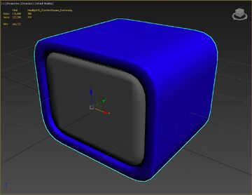
| + | We'll start by using the UV mesh as our reference point. Our conforming mesh needs to cover the hole created here, so we'll make a ring of faces to surround the UV mesh with enough width to not allow any visible gaps between the cutout and the conforming mesh. We'll extend this edge out along the -Y axis (forward from the car body) by a millimetre or two to prevent faces from clipping through the car body, and we'll extrude a ring of faces around the outside of it to connect the mesh to the car body like so:[[File:Conforming Mesh Example 01.png|alt=Conforming Mesh|none|thumb|360x360px|A conforming mesh covering the outside edges of a UV mesh, extruded out in to the -Y axis slightly to avoid clipping through the car body, and with a ring of faces around the outside to avoid it looking like it's floating.|link=https://automation.gamepedia.com/File:Conforming_Mesh_Example_01.png]]Because this fixture is going to have a skinned mesh, we'll need to take that into consideration too. A skinned mesh will have any vertices that are farther than 1.5 mm in the -Y axis conform to the car in the same way as a conforming mesh, so we'll need to match this mesh structure such that the two meshes connect seamlessly. |
||
| − | In 3DS-Max, this is done by applying Material IDs to the faces of the mesh, and assigning a Multi-SubObject Material with Sub-Materials applied to it. |
||
| + | Here is the conforming mesh, with the skinned mesh and UV mesh:[[File:Conforming Mesh and Skinned Mesh Example.jpg|alt=Note that the inner most edge of the Conforming Mesh lines up perfectly with the outer most edge of the Skinned Mesh.|none|thumb|360x360px|Note that the innermost edge of the conforming mesh lines up perfectly with the outermost edge of the skinned mesh.|link=https://automation.gamepedia.com/File:Conforming_Mesh_and_Skinned_Mesh_Example.jpg]]This headlight fixture will also have a glass cover over it, so we'll add that in now. For this example, I've added a small step to the inside of the conforming mesh to add a little bit of detail. The glass cover will then be placed on top. You'll also notice that the outside edge of this headlight has been extruded deep behind the surface; this is so it can be placed on top of other headlights or grilles and not appear to float.[[File:Conforming Mesh Example 02.jpg|alt=Left: Face View of the Conforming Mesh . Right: Wireframe View|none|thumb|Left: Face view of the conforming mesh. Right: Wireframe view.|link=https://automation.gamepedia.com/File:Conforming_Mesh_Example_02.jpg|360x360px]] |
||
| − | ===== Unwraping the Mesh ===== |
||
| − | The next step is to apply an Unwrap to the mesh. We'll be use 3DS-Max's default UVW Map modifier, set it to 'box' projection, and set the length, width, and height dimensions to 2,2,2. This is an important dimension if your fixture mod intends to use our default materials, as these materials assume the UVs of the fixture conform to this setting. |
||
| + | ===== Unwrapping the Mesh ===== |
||
| − | Basically what this is doing is mapping every face on the mesh so that the 0-1 areas of the UV Map are 2cm². |
||
| + | The next step is to unwrap the mesh. We'll be using 3ds Max's default UVW Map modifier, setting it to 'box' projection (cube projection in Blender), and setting the length, width, and height dimensions all to 2. This value is important if your fixture mod intends to use our default materials, because said materials assume that the UVs of the fixture conform to this setting. |
||
| − | + | Basically, what this is doing is UV mapping the mesh so that the 0-1 areas of the UV map are 2cm².[[File:Conforming Mesh Example 03.jpg|alt=The finished Conforming Mesh with an UVW Map modifier set to a box 2,2,2 projection.|none|thumb|The finished conforming mesh with a UVW Map modifier set to a 2, 2, 2 box projection.|link=https://automation.gamepedia.com/File:Conforming_Mesh_Example_03.jpg|360x360px]]We'll go over the import process and material setup after we've created all of the meshes. |
|
==== Creating a Skinned Mesh ==== |
==== Creating a Skinned Mesh ==== |
||
| − | A |
+ | A skinned mesh is the most complicated mesh in a fixture. It follows the same rules as the conforming Mesh in terms of overall mesh structure and UV mapping, but the manner in which it conforms to the car is more nuanced. |
| − | The vertices of a |
+ | The vertices of a skinned Mesh will conform to the car in the same manner as the conforming mesh if those vertices are within 1.5 mm of the Y axis. This is useful for having these parts of the mesh connect to a conforming mesh, as they will conform the same in that area.[[File:Skinned Mesh Example 01.jpg|alt=Note that only the vertices on the lower most edge of this mesh will conform as if they were part of a Conforming Mesh, as they are within 0.15cm of the Y-axis. Also note that these vertices will maintain this offset from the Y-axis even after they have conformed to the car. Thus the Conforming Mesh will need to extrude out at least as far, to cover up these vertices.|none|thumb|Note that only the vertices on the lowermost edge of this mesh will conform as if they were part of a conforming mesh, as the rest are farther than 1.5 mm from the body surface. Also note that these vertices will maintain this offset from the Y axis even after they have conformed to the car; thus, the conforming mesh will need to extend at least as far to connect to these vertices.|link=https://automation.gamepedia.com/File:Skinned_Mesh_Example_01.jpg|480x480px]]The rest of the mesh will conform relative to their skinned bones and weights. For this example, I've created a Skinned Mesh with 4 bones, and weighted them like so:<gallery mode="nolines" widths="360" heights="180"> |
| + | File:Skinned Mesh Example 02.jpg|Each bone is weighted to the parts of the skinned mesh that should retain their proportions, with the intermediary vertices weighted smoothly between bones. |
||
| + | File:Animated2.gif|The bones in motion. |
||
| + | </gallery>The bones are free floating, and are parented only to the bone root. I usually use Dummy Actors for my bones, but you can use a box mesh or whatever works. |
||
| − | Take note that the vertices that conform to the mesh in the same manner as the |
+ | Take note that the vertices that conform to the mesh do so in the same manner as the conforming mesh, but are still weighted to their respective bones. This is because Automation's fixture system uses the distance that these vertices were morphed to determine how far back to conform each bone. If these vertices were weighted to the root bone instead, the fixture would not know how far to morph the skinned sections of the mesh. |
| + | Unreal Engine 4 also requires a bone hierarchy, so I've made a root bone and parented all of the other bones to it. The root bone should not be weighted to any vertices.<gallery mode="nolines" widths="360" heights="240"> |
||
| − | The bones of the ''Skinned Mesh'' should also lie at 0 on the Y axis, as they are rotated when the fixture is set to 'lock to cardinal', and having them offset from 0 would result in strangeness.[[File:Skinned Mesh Example 04.jpg|alt=Top View|none|thumb|Top View|link=https://automation.gamepedia.com/File:Skinned_Mesh_Example_04.jpg]]Take a look at the below image of the skinned mesh on the car (There's also a Conforming Mesh there around the edge, but we'll ignore that for now). The outside edge of vertices are conforming to the car as if they were part of a Conforming Mesh, and the rest of the mesh is conforming as per their bone weights:[[File:FixtureOnCar01.png|none|thumb|link=https://automation.gamepedia.com/File:FixtureOnCar01.png]] |
||
| + | File:Skinned Mesh Example 03.jpg|From a front view, you can see that the bones are centred on their respective elements. |
||
| + | File:Skinned Mesh Example 04.jpg|Top view. |
||
| + | </gallery>Take a look at the image below of the skinned mesh on the car (there's also a conforming mesh there around the edge, but we'll ignore that for now). The outer ring of vertices is conforming to the car as if it was part of a conforming mesh, and the rest of the mesh is conforming as per their bone weights: |
||
| + | [[File:FixtureOnCar01.png|link=https://automation.gamepedia.com/File:FixtureOnCar01.png|frameless|360x360px]] |
||
| − | ===== Applying Materials ===== |
||
| − | As with the ''Conforming Mesh'', assign materials to your mesh with material IDs and a multi-sub-object material. |
||
| − | ===== |
+ | ===== Unwrapping the Mesh ===== |
| − | Assign the same |
+ | Assign the same box map (with a scale of 2, 2, 2) as you did with the conforming mesh. |
==== Creating an Additional Mesh ==== |
==== Creating an Additional Mesh ==== |
||
| − | An ''Additional Mesh'' is |
+ | An ''Additional Mesh'' is a simple mesh with no skin or morphs that does not deform in any way. The Additional Mesh ''does'' rotate around the fixture position, and will maintain its relative position from its pivot point. |
| − | |||
| − | Take the following example. This is an exhaust fixture. Notice that the entirety of the exhaust is offset from the pivot point - this is so this exhaust can hang under the car, as the fixture itself must be placed on the car but the exhaust in this instance must be under the car:[[File:Additional Mesh Example 01.jpg|alt=3D View.|none|thumb|3D View.|link=https://automation.gamepedia.com/File:Additional_Mesh_Example_01.jpg]][[File:Additional Mesh Example 02.jpg|alt=Front view.|none|thumb|Front view.|link=https://automation.gamepedia.com/File:Additional_Mesh_Example_02.jpg]] |
||
| − | |||
| − | === Fixture Mod setup within Unreal Engine 4 === |
||
| − | This step assumes that the correct version of Unreal Engine is installed and configured correctly. See [[Modding]] for more information on the correct version of Unreal Engine to use and how to view mod content folders. Also see [https://docs.unrealengine.com/latest/INT/Engine/Content/FBX/StaticMeshes/#importmesh the official Unreal Engine documentation on importing .FBX files]. |
||
| − | |||
| − | ==== Creating your Fixture Mod Plugin ==== |
||
| − | With the correct version of Unreal Engine opened with our modding tool project and plugins loaded, you should be able to select 'create mod' from the top menu bar (step 1). From there, select 'New Fixture' (step 2), then give your mod a name (step 3) and a description (step 4), then click 'create mod' (step 5).[[File:Creating Fixture Mod.jpg|none|thumb|link=https://automation.gamepedia.com/File:Creating_Fixture_Mod.jpg]]You should now see a file called 'NewFixture' within a new folder: |
||
| − | [[File:Example blank fixture mod.jpg|none|thumb]] |
||
| − | |||
| − | ==== Importing files to Unreal Engine ==== |
||
| − | |||
| − | ===== Mesh Importing ===== |
||
| − | There are several ways to import your sub-meshes to this mod folder. The easiest is to simply navigate to the folder you want to import your files in the Content Browser, then click the 'import' button to import files to that folder: |
||
| − | [[File:Import files button.gif|none|thumb]] |
||
| − | select the meshes you want to import, and click 'open'. |
||
| − | |||
| − | ''UV Meshes'', ''Conforming Meshes'', and ''Additional Meshes'' should be imported as 'Static meshes' ('Skeletal Mesh' is un-ticked in the import dialogue), while ''Skinned Meshes'' should be imported as 'Skeletal Meshes' '(Skeletal Mesh' is ticked in the import dialogue). |
||
| − | |||
| − | Note that 'Skeletal Meshes' will import with additional 'Skeleton' and 'Physics Asset' files. ''These are important''. You don't need to do anything with them, but don't delete them.[[File:Import Dialogue Example 01.jpg|alt=An example import dialogue for a Skinned Mesh. This should be un-ticked for other sub-mesh types|none|thumb|An example import dialogue for a ''Skinned Mesh''. This should be un-ticked for other sub-mesh types|link=https://automation.gamepedia.com/File:Import_Dialogue_Example_01.jpg]]Note that 'Import Materials' is also un-ticked, as we do not want to import any materials from our authoring software. |
||
| − | |||
| − | The final set of imported files in Unreal Engine should look like this:[[File:Example Imported.jpg|alt=Note that this example does not include an Additional Mesh.|none|thumb|Note that this example does not include an ''Additional Mesh''.|link=https://automation.gamepedia.com/File:Example_Imported.jpg]]Once your files are imported, it's important to set '''''CPU Access''''' to true for all ''Static Meshes''. You can do this by selecting every Static Mesh, right-clicking on it and selecting 'Set meshes to allow CPU access'.[[File:Allow CPU access.jpg|none|thumb|link=https://automation.gamepedia.com/File:Allow_CPU_access.jpg]] |
||
| − | |||
| − | ===== Assigning Default Materials and Material Slot names ===== |
||
| − | ''This step assumes a basic understanding of the [https://docs.unrealengine.com/latest/INT/Engine/Content/Types/StaticMeshes/Editor/ Static Mesh] editor and [https://docs.unrealengine.com/latest/INT/Engine/Animation/Persona/Modes/Mesh/ Skeletal Mesh] editor.'' |
||
| + | Take the following example: an exhaust fixture. Note that the entirety of the exhaust is offset from the pivot point—this is so that it can hang under the car, since the fixture itself must have its pivot point ''on'' the car.<gallery mode="nolines" widths="360" heights="240"> |
||
| − | ====== Assigning Material Slot names ====== |
||
| + | File:Additional Mesh Example 01.jpg|3D view. |
||
| − | The new fixture material swap system in Automation relies on the name of the material slots within the mesh components to define what materials can be applied to the fixture. |
||
| + | File:Additional Mesh Example 02.jpg|Front view. |
||
| + | </gallery> |
||
| + | === Additional Considerations === |
||
| − | Therefore, Assigning the correct materials to the meshes is only important for the initial selection and loading of that fixture. In this manner, it is possible to have custom materials applied to your fixture while still being compatible with Automation's fixture switching UI. |
||
| + | ==== Unwrapping reflector lights ==== |
||
| − | The fixture switching UI in Automation relies on the names of the material slots on the sub-meshes to decide what category of materials the player has to select from. |
||
| + | If your fixture is a light that contains a reflector surface (such as an incandescent bulb), there are some special considerations. |
||
| − | + | Let's take a look at this fixture as an example: |
|
| − | *panel_# |
||
| + | [[File:Screenshot_2021-01-18_131739.png|frameless|360x360px]] |
||
| − | [[File:Panel -.png|alt=picks from the car body colours|none|thumb|picks from the car body colours]] |
||
| + | Several things are of note with regards to light components: |
||
| − | *glass_# |
||
| + | * The bulbs themselves should be unwrapped as a single point with zero scale exactly at UV coordinate <code>0.5,0.5</code> (the UV is scaled to a single point in the very center). |
||
| − | [[File:Glass -.png|alt=for when you can see through to another part of the fixture|none|thumb|for when you can see through to another part of the fixture]] |
||
| + | * The main reflector surface should be unwrapped such that each quad face fills the entirety of the <code>0-1</code> UV coordinate space (<code>Reset UV projection</code> in Blender). |
||
| + | * The side walls of the reflector (and any other part of the reflector that you want to have vertical or horizontal lines on) should be unwrapped as a single point with zero scale exactly at UV coordinate <code>0,1</code> (the UV is scaled to a single point in the bottom left corner). |
||
| + | * Parts of the reflector that should appear flat should be unwrapped as a single point with zero scale exactly at UV coordinate <code>0,0</code> (the UV is scaled to a single point in the top left corner). |
||
| + | ==== Applying materials to a light component ==== |
||
| − | *opaqueglass_# |
||
| + | The bulb and reflector for each light should be assigned to the same material slot to save on draw calls. Each separate light, however, should be a different material slot for freedom of choice in terms of light configurations. |
||
| + | ==== Unwrapping radial glass ==== |
||
| − | [[File:Opaqueglass -.png|alt=for when you have a piece of glass that should not be seen through underneath another piece of glass|none|thumb|for when you have a piece of glass that should not be seen through underneath another piece of glass]] |
||
| + | For light glass with a radial pattern, unwrap the glass so that the radial pattern fills the whole UV space as a single texture. |
||
| + | == Fixture setup within Unreal Engine 4 == |
||
| − | *grill_# |
||
| + | This step assumes that the correct version of Unreal Engine is installed and configured correctly. See [[Modding]] for more information on the correct version of Unreal Engine to use and how to view mod content folders. Also see [https://docs.unrealengine.com/latest/INT/Engine/Content/FBX/StaticMeshes/#importmesh the official Unreal Engine documentation on importing FBX files] for more information. |
||
| + | === Creating your Fixture Mod Plugin === |
||
| − | [[File:Grill -.png|none|thumb|alt=Textures for the interior of grill and vent fixtures]] |
||
| + | Using the correct version of Unreal Engine, with our modding tool project opened and plugins loaded, select 'Create Mod' from the top menu bar. |
||
| + | [[File:UE4ModCreation 02.gif|none|thumb|1) Select the blank project. 2) Give your mod a unique name. 3) Fill out your name and a description of this mod. 4) Create the mod.|360x360px|alt=]] |
||
| + | === Importing Files === |
||
| − | *roundglass_# |
||
| + | There are several ways to import your sub-meshes to this mod folder. The easiest is to simply navigate to the folder you want to import your files in the Content Browser, then click the 'Import' button to import files to that folder, select the meshes you want to import, and click 'Open'. |
||
| + | [[File:Import_files_button.gif|frameless|360x360px]] |
||
| − | [[File:Roundglass -.png|alt=A transparent glass type with radial detailing. Round glass applies to the mesh in the traditional UV sense, so use a planar map to unwrap this part of the mesh if you intend to use this.|none|thumb|a transparent glass type with radial detailing. round glass applies to the mesh in the traditional UV sense, so use a planar map to unwrap this part of the mesh if you intend to use this.]] |
||
| − | ''License Plate textures:'' |
||
| + | UV meshes, conforming meshes, and additional meshes should be imported as static meshes ('Skeletal Mesh' is un-ticked in the import dialogue), while skinned meshes should be imported as skeletal meshes ('Skeletal Mesh' is ticked in the import dialogue). |
||
| − | * numberplatenarrow_# |
||
| + | Note that 'Skeletal Meshes' will import with additional 'Skeleton' and 'Physics Asset' files. ''These are important''. You don't need to do anything with them, but don't delete them.[[File:Import Dialogue Example 01.jpg|alt=An example import dialogue for a Skinned Mesh. This should be un-ticked for other sub-mesh types|none|thumb|An example import dialogue for a skinned mesh. This should be unticked for other sub-mesh types.|link=https://automation.gamepedia.com/File:Import_Dialogue_Example_01.jpg|383x383px]]Note that 'Import Materials' is also unticked, as we do not want to import any materials from the modelling software. |
||
| + | The final set of imported files in Unreal Engine should look like this:[[File:Example Imported.jpg|alt=Note that this example does not include an Additional Mesh.|none|thumb|Note that this example does not include an additional mesh.|link=https://automation.gamepedia.com/File:Example_Imported.jpg|392x392px]]Once your files are imported, it's important to set 'CPU Access' to true for ''all static meshes''. You can do this by selecting every static mesh, right-clicking on it and selecting 'Set Meshes to Allow CPU Access'. |
||
| − | [[File:Numberplatenarrow -.png|none|thumb|293x293px|alt=North American spec plates, 1024×2048 px textures]] |
||
| + | [[File:Allow_CPU_access.jpg|link=https://automation.gamepedia.com/File:Allow_CPU_access.jpg|frameless|240x240px]] |
||
| + | === Default Materials and Material Slots === |
||
| − | * numberplatewide_# |
||
| + | '''''Note:''' This step assumes a basic understanding of UE4's [https://docs.unrealengine.com/latest/INT/Engine/Content/Types/StaticMeshes/Editor/ Static Mesh] editor and [https://docs.unrealengine.com/latest/INT/Engine/Animation/Persona/Modes/Mesh/ Skeletal Mesh] editor. Alternatively, material slots can be named appropriately within a 3D modelling program of choice.'' |
||
| + | The fixture material system in Automation relies on the name of the material slots within the meshes to define what materials can be applied to the fixture. Therefore, assigning the correct materials to the meshes is only important for the initial selection and loading of that fixture. In this manner, it is possible to have custom materials applied to your fixture with it still being compatible with Automation's fixture material menu. |
||
| − | * |
||
| + | The fixture material menu in Automation relies on the names of the material slots on the sub-meshes to decide what category of materials the player can select from, with said names in the format <code>category_#</code> (case-sensitive, with '#' being a single- or multiple-digit number of choice). |
||
| − | [[File:Numberplatewide -.png|none|thumb|253x253px|alt=European-spec license plates, 2048×512 px textures]] |
||
| + | The available categories for fixture materials are as follows:<gallery mode="nolines" widths="240" heights="120" perrow="4"> |
||
| − | ''Note that these names are case-sensitive.'' |
||
| + | File:Panel -.png|alt=panel|<code>panel</code> (car body colours and some other opaque materials) |
||
| + | File:Opaqueglass -.png|alt=opaqueglass|<code>opaqueglass</code> (opaque light glass; ideal for non-bulb lights) |
||
| + | File:Grill -.png|alt=grill|<code>grill</code> (for transparent and opaque grill patterns in addition to <code>panel</code> materials) |
||
| + | File:Glass -.png|alt=glass|<code>glass</code> (transparent and translucent light glass in addition to <code>opaqueglass</code>, <code>panel</code>, and <code>grill</code> materials; this category provides the most freedom in terms of material choice) |
||
| + | File:Roundglass -.png|alt=roundglass|<code>roundglass</code> (transparent light glass with radial detailing; this material applies to a mesh in the traditional UV sense, so use a planar map to unwrap this part of the mesh if you intend to use this) |
||
| + | File:Screenshot 2021-01-18 151206.png|alt=bulb|<code>bulb</code> (for reflector lights; requires special UV unwrapping) |
||
| + | File:Numberplatenarrow -.png|alt=numberplatenarrow|<code>numberplatenarrow</code> (North American license plate format) |
||
| + | File:Numberplatewide -.png|alt=numberplatewide|<code>numberplatewide</code> (European license plate format) |
||
| + | </gallery>If you only have a single slot for a fixture material category, you still need a number for it. This number scales infinitely, meaning a fixture can have many separate slots of a single category assigned to it. A fixture's sub-meshes cannot share the same name on its material slots. If a fixture contains meshes with duplicate slot names, they will appear as a single material slot in-game (this can be used to merge slots on, for example, a conforming and additional mesh). |
||
| + | With light fixtures, the names of the slots for the corresponding pair of glass and reflector material slot names should share the same number. For example, a fixture with two lights would have <code>glass_01</code> (or just <code>glass_1</code>) and <code>bulb_01</code>, and <code>glass_02</code> and <code>bulb_02</code>. |
||
| − | If you only have a single version of a fixture material category, you still need to have a number, where '#' is replaced with a number. This number scales infinitely, meaning a fixture can have many separate panel/glass/grill slots assigned to it. A Fixture's sub-meshes cannot share the same name on its material slots. If a fixture contains meshes with duplicate slot names, they will appear incorrect in-game. |
||
| − | + | Below is a headlight's conforming mesh with its default materials set and the names of its material slots set to their respective types. The workflow for additional meshes should be identical.<gallery mode="nolines" widths="360" heights="180"> |
|
| + | File:Headlight Conforming Mesh Materials Setup 01.jpg |
||
| + | File:Material 02.jpg|Close-up view of the materials |
||
| + | </gallery>The Skeletal Mesh editor looks a little different, but the slot naming conventions are the same: |
||
| + | [[File:Skeletal_Mesh_Slot_example_01.jpg|link=https://automation.gamepedia.com/File:Skeletal_Mesh_Slot_example_01.jpg|frameless|360x360px]] |
||
| − | ====== Assigning Default Materials ====== |
||
| − | While the slot names define what materials the player can choose from in-game, it doesn't define what material gets first loaded when the player places the fixture on the car. |
||
| + | ==== Assigning Default Materials ==== |
||
| − | When the fixture is first placed on the car, it loads the material that is set in that fixture's sub-mesh default materials. For the sub-mesh examples above, you can see that the slot names have been set and the material slots also have materials set in them. |
||
| + | While the slot names define what materials the player can choose from in-game, it doesn't define what material first gets loaded when the fixture is spawned in. |
||
| + | When the fixture is first placed on the car, it loads the material that is set in that fixture's sub-mesh default materials. For the sub-mesh examples above, you can see that not only have the slots been named appropriately, they also have materials assigned to them. Therefore, for all your fixture sub-meshes, default materials should be applied. (They're not strictly necessary, but your fixtures deserve better than the default grey checkered material.) |
||
| − | Therefore, for all your fixture sub-meshes, you also need to apply their default materials. |
||
| − | To find where all the materials available in-game are, open up the |
+ | To find where all the materials available in-game are, open up the <code>CarMaterialUtils</code> blueprint (located in <code>Content</code> -> <code>Utility</code>), and open the 'Get Materials from Slot' function. There, you can view the list of each material that gets assigned to each slot, find them in the content folder, and assign them to your mesh as the default material. Note, though, that these steps are only to find where the default materials are. We do not use the Utils blueprint itself to assign materials to fixtures. |
| + | To do this, open <code>CarMaterialUtils</code>... |
||
| − | Note though that these steps are only to find where the default materials are. We do not use the Utils blueprint itself to assign materials to fixtures. |
||
| + | [[File:Carmaterialutils01.png|frameless|360x360px]] |
||
| − | To do this, open Utils: |
||
| − | [[File:Utils bp location.gif|none|thumb]] |
||
| − | Then open 'Get Fixture Materials from Slot', located in Utils > Car Painting > GetFixtureMaterialsFromSlot: |
||
| − | [[File:Get fixture mats from slot location.gif|none|thumb]] |
||
| − | From there, select the corresponding materials array for the material type you want to apply to your sub-mesh: |
||
| − | [[File:Util material arrays.gif|none|thumb]] |
||
| − | And in the details panel you'll see an array of the materials used for that slot type: |
||
| − | [[File:Util material array.gif|none|thumb]] |
||
| − | By expanding that, you can see the materials, and by selecting the small magnifying glass icon, view that material in the Content Browser: |
||
| − | [[File:Find mat in content browser.gif|none|thumb]] |
||
| − | and from there apply it to your sub-mesh. |
||
| + | ...then open 'Get Fixture Materials from Slot', located in <code>CarMaterialUtils</code> -> <code>Car Painting</code> -> <code>GetFixtureMaterialsFromSlot</code>. |
||
| − | Alternatively, here is a list of all the currently-used materials, and their locations in the content browser: |
||
| − | * '''Panel:''' |
||
| − | ** M_Carpaint (located in: Content > Cars > Materials > NewMaterials > CarPaint) |
||
| − | ** M_BlackPlastic (located in: Content > Environments > BuildingInteriors > Assets > ArtTest > Materials) |
||
| − | ** M_BlackPlastic_ShinyBlack (located in: Content > Fixtures > FixtureMats) |
||
| − | ** MI_Metal_Chrome_01_Bright (located in: Content > Cars > Materials > NewMaterials > Metal) |
||
| − | * '''Grille:''' |
||
| − | ** M_Grill (located in: Content > Fixtures > FixtureMats) |
||
| − | ** M_Grill02 (located in: Content > Fixtures > FixtureMats) |
||
| − | ** M_Grill03 (located in: Content > Fixtures > FixtureMats) |
||
| − | ** M_Grill04 (located in: Content > Fixtures > FixtureMats) |
||
| − | ** M_Grill05 (located in: Content > Fixtures > FixtureMats) |
||
| − | ** M_Grill_Trans (located in: Content > Fixtures > FixtureMats) |
||
| − | ** M_Grill02_Trans (located in: Content > Fixtures > FixtureMats) |
||
| − | ** M_Grill03_Trans (located in: Content > Fixtures > FixtureMats) |
||
| − | ** M_Grill04_Trans (located in: Content > Fixtures > FixtureMats) |
||
| − | ** M_Grill05_Trans (located in: Content > Fixtures > FixtureMats) |
||
| − | ** M_HeadLightGlass_Clear (located in: Content > Fixtures > FixtureMats) |
||
| − | ** TransparentMat_Inst (located in: Content > Cars > Materials > SharedMaterials) |
||
| − | * '''Glass:''' |
||
| − | ** M_Indicator_SmoothGlass (located in: Content > Fixtures > FixtureMats) |
||
| − | ** M_Indicator_SmoothPlastic (located in: Content > Fixtures > FixtureMats) |
||
| − | ** M_Indicator_RoughPlastic (located in: Content > Fixtures > FixtureMats) |
||
| − | ** M_BrakeLight_SmoothGlass (located in: Content > Fixtures > FixtureMats) |
||
| − | ** M_BrakeLight_SmoothPlastic (located in: Content > Fixtures > FixtureMats) |
||
| − | ** M_BrakeLight_RoughPlastic (located in: Content > Fixtures > FixtureMats) |
||
| − | ** M_ReversingLight_SmoothGlass (located in: Content > Fixtures > FixtureMats) |
||
| − | ** M_ReversingLight_SmoothPlastic (located in: Content > Fixtures > FixtureMats) |
||
| − | ** M_ReversingLight_RoughPlastic (located in: Content > Fixtures > FixtureMats) |
||
| − | * '''Opaque Glass:''' |
||
| − | ** MI_Metal_Chrome_01_Bright (located in: Content > Cars > Materials > NewMaterials > Metal) |
||
| − | ** MI_Metal_Chrome_02_Bright (located in: Content > Cars > Materials > NewMaterials > Metal) |
||
| − | ** MI_Metal_Chrome_03_Dark (located in: Content > Cars > Materials > NewMaterials > Metal) |
||
| − | ** MI_Metal_Chrome_Dirt_03_Dark (located in: Content > Cars > Materials > NewMaterials > Metal) |
||
| − | ** MI_Reflector_Orange (located in: Content > Cars > Materials > NewMaterials > Reflector) |
||
| − | ** MI_Reflector_Red (located in: Content > Cars > Materials > NewMaterials > Reflector) |
||
| − | ** M_Headlight_Indicator (located in: Content > Fixtures > FixtureMats) |
||
| − | ** M_HeadlightMat_04 (located in: Content > Fixtures > FixtureMats) |
||
| − | ** M_BrakeLightSmoothPlasticOpaque (located in: Content > Fixtures > FixtureMats) |
||
| − | ** M_Indicator_SmoothPlasticOpaque (located in: Content > Fixtures > FixtureMats) |
||
| − | ** M_ReversingLightSmoothPlasticOpaque (located in: Content > Fixtures > FixtureMats) |
||
| − | * '''Round Glass:''' |
||
| − | ** M_RadialTaillight (located in: Content > Fixtures > FixtureMats) |
||
| − | ** M_RadialTaillight2 (located in: Content > Fixtures > FixtureMats) |
||
| − | ** M_RadialTaillight3 (located in: Content > Fixtures > FixtureMats) |
||
| − | ** M_HeadLightGlass_StraightWaves (located in: Content > Fixtures > FixtureMats) |
||
| + | [[File:Carmaterialutils02.png|frameless|424x424px]] |
||
| − | ==== Creating the Fixture Blueprint ==== |
||
| − | If your Fixture Mod only contains one fixture with no variants, you may skip this step, as the '[[Fixture Mods#Creating your Fixture Mod Plugin|Creating your Fixture Mod Plugin]]' step should have created a fixture blueprint in your mod folder for you (unless you did not start your mod with the mod type of 'fixture mod', then please continue). |
||
| + | From there, select the corresponding materials array for the material category you want to apply to your sub-mesh from the Local Variables tab, and in the details panel you'll see an array of the materials used for that slot type. By expanding that, you can see the materials, and by selecting the small magnifying glass icon, view that material in the Content Browser, and from there apply it to your sub-mesh. |
||
| − | When creating a new fixture, you will need to either duplicate a blueprint from another fixture (the first fixture blueprint created by '''Creating your Fixture Mod Plugin''<nowiki/>' will work for this), or create a child blueprint from A_Fixture (located in Content/Cars/Blueprints/Fixtures) by right-clicking on it and selecting 'Create Child Blueprint Class'. The Fixture Blueprint then needs to be moved to the fixture's sub-folder location.[[File:Fixture Imported Example.jpg|none|thumb|link=https://automation.gamepedia.com/File:Fixture_Imported_Example.jpg]]Your fixture folder should now look like this:[[File:Example Fixture Folder 01.jpg|none|thumb|link=https://automation.gamepedia.com/File:Example_Fixture_Folder_01.jpg]] |
||
| + | === Creating and Setting Up the CPP File === |
||
| + | Right-click in the content browser, and from the 'Camso' sub-menu, select the 'Fixture Preview Data' option. You should now have a fixture CPP file in your content browser.[[File:UE4ModCreation 25.gif|none|thumb]] |
||
| + | Open the CPP file. You should get something like this: |
||
| + | [[File:UE4ModCreation_26.jpg|frameless|478x478px]] |
||
| − | ===== Assigning settings within the Fixture Blueprint ===== |
||
| − | Open the Fixture Blueprint. You should be confronted with the following:[[File:FixtureExampleSettings.png|alt=A blank fixture blueprint with only the relevant settings shown|none|thumb|A blank fixture blueprint with only the relevant settings shown|link=https://automation.gamepedia.com/File:FixtureExampleSettings.png]] |
||
| + | Fill out the 'Meshes' section with the meshes you've made, leave the 'Text' data empty, generate a GUID and Family GUID (or copy the family GUID if you're making a variant), and set the 'Fixture' settings to the relevant info as laid out near the top of this page. Finally, in the 'Path' section, make sure there is one item in the array, and fill it with <code>A_Fixture</code>. '''''This is important; your fixture will not work if this is not filled correctly.''''' |
||
| − | ===== Assigning Meshes within the Fixture Blueprint ===== |
||
| − | Assign your meshes to their respective slots by selecting them in the Content Browser then clicking on the small arrow in the fixture blueprint next to the associated slot, or by dragging and dropping the mesh in to the slot. You can also search for the mesh and assign it within the dialogue box.[[File:Animated.gif|none|thumb|link=https://automation.gamepedia.com/File:Animated.gif]] |
||
| − | ===== Assign the GUIDs ===== |
||
| − | Generate a GUID for the fixture and the family. If this fixture is part of a family, then copy-paste the family GUID instead. The Fixture GUID should always be unique.[[File:Animated1.gif|none|thumb|link=https://automation.gamepedia.com/File:Animated1.gif]] |
||
| − | ===== Adjust fixture blueprint settings ===== |
||
| − | *Assign the Fixture Type |
||
| − | *Assign the Centre Snap Distance |
||
| − | *Assign the 'Lock Normal to Cardinal' setting |
||
| − | Consult the [[Fixture Mods#Fixture Settings|Fixture Mods]] step for further descriptions on these settings. |
||
| − | ====Compile and Save the Fixture Blueprint==== |
||
| − | Once all your sub-meshes and settings have been applied in the Fixture Blueprint, you have to compile and save that blueprint. |
||
| + | When you're done, you should have something that looks like this:[[File:FixtureExampleSettings.png|alt=Fixture Blueprint|none|thumb|A fixture blueprint with only the relevant settings shown.|link=https://automation.gamepedia.com/File:FixtureExampleSettings.png|333x333px]]Be sure to save your files. |
||
| − | To Compile it, press the 'Compile' button in the Fixture Blueprint (top left of the blueprint editor window).[[File:CompileBP example.jpg|none|thumb|link=https://automation.gamepedia.com/File:CompileBP_example.jpg]]Then either save the blueprint in the same window, or in the Content Browser.[[File:Save Example.jpg|alt=An item needs to be saved if it has a small star icon in the bottom left|none|thumb|An item needs to be saved if it has a small star icon in the bottom left|link=https://automation.gamepedia.com/File:Save_Example.jpg]] |
||
| − | === |
+ | ===Creating the Thumbnail=== |
| + | You should already be here by default when you load up the Automation project. Check the top tab in Unreal and make sure it says 'ThumbnailGeneratorLevel_Fixture'. If you are not in the thumbnail generator level, open it from <code>DeveloperSandbox/ThumbnailGeneratorLevel_Fixture</code>.<gallery mode="nolines" widths="360" heights="240"> |
||
| − | The Fixture Blueprint does not get automagically loaded in to the fixture UI. The UI loads a proxy thumbnail file instead, so we need to generate this proxy file. '''''If the Fixture Blueprint does not have an associated thumbnail, it will not show up in-game.''''' Luckily, we have an automated script to do this. |
||
| + | File:UE4ModCreation 27.gif |
||
| + | File:UE4ModCreation 28.gif |
||
| + | </gallery>From the top menu, open the drop-down next to the 'Play' button and select 'Simulate'. You should now be 'simulating' the level. |
||
| + | [[File:UE4ModCreation_15.gif|frameless|360x360px]] |
||
| − | ===== Open the Thumbnail Generator Level ===== |
||
| − | Open the Thumbnail Generator Level from: 'Content > Developer Sandbox > ThumbnailGeneratorLevel'[[File:Opening the thumb gen level.jpg|none|thumb|link=https://automation.gamepedia.com/File:Opening_the_thumb_gen_level.jpg]] |
||
| − | ===== |
+ | ===== Generate Fixture Thumbnails ===== |
| − | Select the Fixture Thumbnail Generator from the World Outliner, and add your fixture blueprint to the ' |
+ | Select the Fixture Thumbnail Generator from the World Outliner, and add your fixture blueprint to the 'Fixture Previews to Generate' array (by first clicking the 'plus' icon, then putting the fixtures you have created into the list). Repeat this process for every fixture you have created. It does not matter if these fixtures are of the same family or not. Then, select 'Export Preview' to generate the Thumbnail file.[[File:Fixture thumb gen 02.gif|none|thumb|alt=Note that I am connected to source control in this .gif, so I have red crosses in the top right corner of the items in the Content Browser. If you do not see this, do not worry. Also ignore that im putting blueprints in to the 'fixtures to generate' array, this is depreciated. put your .cpp files in the 'previews' one.|Note that I am connected to source control in this .gif, which explains the red checkmarks in the top right corner of the items in the Content Browser. If you do not see this, do not worry.|link=https://automation.gamepedia.com/File:Fixture_thumb_gen_02.gif|389x389px]] |
| + | Because these files are created by the modding tools, they need to be manually saved (even if no asterisks are present). |
||
| − | ===== Generate the Thumbnail and CPP file ===== |
||
| − | Select 'Export Preview' to generate the Thumbnail file and FixturePreviewCPP files. These files should be created within a 'thumbnail' folder within their respective fixture sub-folders.[[File:Untitled-8.gif|none|thumb|link=https://automation.gamepedia.com/File:Untitled-8.gif]]You should see a new folder in your fixture folder with the created thumbnail files in them. Navigate to those files and right click -> save. Because these files are created by the modding tools, they need to be manually saved. |
||
Your fixture mod is now ready to be shared! |
Your fixture mod is now ready to be shared! |
||
| − | == Cooking and |
+ | == Cooking and sharing your mod == |
| − | To use the mod you have just created, you need to 'share' it. See the main Modding page on how to share your mod |
+ | To use the mod you have just created, you need to 'share' it. See [[Modding#Cooking|the main Modding page]] on how to share your mod. |
| − | == Additional |
+ | == Additional notes == |
| − | *Fixtures should not have any vertices along the centre axes to avoid any miscalculation by the fixture gizmo. |
+ | *Fixtures should not have any vertices along the centre axes to avoid any miscalculation by the fixture gizmo. If the game casts a ray through the centre line of the car, it may miss the two halves of the car and return a false positive of the fixture being out of bounds. Offsetting your vertices slightly will avoid this. Additional meshes are the sole exception to this rule, as they do not conform in any way. |
| + | *If you're testing out a fixture and the meshes it uses haven't been finalized, you can use UE4's 'Reimport' function to replace the existing mesh with a newer version of it. All the materials already assigned to the mesh will be preserved, as will its reference in the blueprint, saving you the trouble of manually reimporting a mesh and having to reassign materials and put it into the blueprint again. This works for [[Car Body Mods|car body meshes]] as well. |
||
| − | *Is CPU Access still turned on for all ''Static Meshes''? If your mod causes a crash, this might be un-ticked. It does that sometimes. Re-tick it, and try again. |
||
| + | *Is CPU access still turned on for all static meshes? If your mod causes a crash or isn't visible in-game, this might be unticked. It does that sometimes; re-enable it and try again. |
||
| + | *If the first fixture in a thumbnail generation array ends up with an unusually sparkly thumbnail, this can be fixed by giving it an additional duplicate array entry (which forces UE4 to render the thumbnail again normally). |
||
== See Also == |
== See Also == |
||
* [[Badge Fixture Mods]] |
* [[Badge Fixture Mods]] |
||
| + | *[[Mods and the Beam.NG Exporter]] |
||
Revision as of 06:07, 19 July 2021
Overview
A fixture is a collection of files, for which a cpp file serves as the parent file. All the settings for a fixture are inside this cpp file.
Fixtures are comprised of up to 4 optional sub-meshes (a UV mesh, conforming mesh, skinned mesh, and additional mesh) depending on the type of fixture:
- A UV mesh is the silhouette of the cutout hole that a fixture makes in a car body.
- A conforming mesh (e.g. grilles, outer light glass, or body moulding) will deform to the shape of the body.
- A skinned mesh (e.g. light internals) will maintain its relative internal shapes, but will conform roughly to the shape of the body.
- An addditional mesh (e.g. mirrors) will retain its shape no matter where it is placed on the body.
Fixtures need material slots set up correctly to look as intended, and preview thumbnails to appear in-game.
Performance considerations
The performance of fixtures (and bodies) in UE4 is a constant discussion of balance.
There is a performance impact to poly count with fixtures in that a ray is cast to the body for every vertex; the more vertices there are in a mesh, the longer it'll take to conform to the body. This is why you'll see more detailed fixtures sit there for a few seconds before conforming to the car.
This is doubly so for fixtures that cut into the body—a UV mesh's vertices are raycast to the car on every frame while you're dragging the fixture around. UV meshes impact performance significantly with a higher poly count; try to keep UV meshes as low-poly as possible.
For optimal performance:
- Keep UV meshes lower than 100 triangles. With between 100 and 150 triangles, the fixture may lag when being dragged around; any higher and it will lag too much to use properly.
- Try to keep conforming meshes lower than 5,000 triangles. Higher-resolution meshes take longer than usual to conform to the car once they are placed.
Fixture blueprints
A Fixture is composed of a Blueprint that contains the fixture settings and sub-meshes.
Fixture Settings
Meshes (more on these later):
- Conforming Mesh - Defines the Static Mesh sub-mesh used by this fixture.
- UV Mesh - Defines the UV Mesh sub-mesh used by this fixture.
- Skinned Mesh - Defines the Skinned Mesh sub-mesh used by this fixture.
- Additional Mesh - Defines the Additional Mesh sub-mesh used by this fixture.
Text:
- Text Data - Currently not used.
Fixture Preview:
- GUID - Unique identifier for this fixture.
- Family GUID - Identifier for this fixture family. This should be unique to every other family GUID, and identical to every other variant of this fixture.
Fixture:
- Fixture Type - What category this fixture should be in (e.g. headlight, aerial, grille, etc).
- Centre Snap Distance - Defines at what distance, in cm, the fixture will snap to the centre line of the car (10 by default).
- Lock Normal to Cardinal- Determines whether the fixture will conform to one of the five cardinal directions in 3d space (forwards, backwards, left, right, or upwards) by default. A non-cardinal-locked fixture will simply face in the direction of the surface on which it is placed. Cardinal locking is useful for fixtures such as lights and mirrors, since it ensures that they don't face in (or conform to) odd directions.
- Export Breakability Override - Certain categories of fixtures can break off when damaged in BeamNG.drive. This setting lets you force a fixture to be breakable or unbreakable.
- Fixture Shape - Used to filter fixtures by rectangular, round, or complex shapes. Mostly used for lights.
- Year - Used to filter fixtures by year. Useful for era-specific fixtures, such as sealed beam headlights.
- Use This Fixture as Family Preview - if you have many variants of a fixture, enabling this setting for one variant will make it the one that shows up in the main fixture menu (overriding the first fixture as per alphabetical order).
Path:
- Fixture Class - Set this to
A_Fixtureto ensure that the fixture works as intended in-game.
Fixture Sub-Meshes
UV Mesh
The UV Mesh (imported as a Static Mesh in UE4) is a flat silhouette that tells the fixture to cut a hole into the car body. You will only need vertices along the outside edges of the UV mesh, and an UV mesh is only required if your fixture intends to cut into the car.
Conforming Mesh
The Conforming Mesh (imported as a Static Mesh in UE4) is a mesh where each vertex is deformed to match the surface of the car body. It is also a required mesh if the fixture has a UV mesh, as the conforming mesh is used to cover the jagged edge of the hole created by the UV mesh. A conforming mesh that could logically be placed on top of other fixtures should also have its outside edges extend beneath the body; the default distance for this extrusion is slightly farther than 10 cm.
Skinned Mesh
The Skinned Mesh (imported as a Skeletal Mesh in UE4) is used when you have parts of a fixture that should conform to the rough shape of the car, but also retain the dimensions and ratios of any individual components. A skinned mesh will have a bone for each element that is parented to a root bone.
All vertices of the skinned mesh that are within 1.5 mm of the car body surface will conform to the car as if they were part of a conforming mesh. Because of this, there may be a small gap of at least 1 mm between the edge of the skinned mesh and the car body. To cover up this gap, a conforming mesh is used to connect the edge of the skinned mesh with the car body.
Additional Mesh
The Additional Mesh (imported as a Static Mesh in UE4) does not deform in any way and will remain in place relative to the location of the fixture. An additional mesh has no skin or bones, and no part of it will deform to the shape of the car. Examples of additional meshes are exhaust tips and wing mirrors.
Modelling a fixture
Note: This how-to assumes a general understanding of polygonal 3D modelling software. Any 3D modelling package will do, as no custom scripts are required to author fixture meshes.
Hard Rooster has created a full video series for fixture modding in Blender.
The full series can be found here.
Fixture Orientation
Fixtures are oriented in the following manner in a 3D modelling program. Note how the negative Y axis faces forwards.

Fixtures come out of the car towards the -Y axis. -X is left, +X is right, +Z is up, and -Z is down.
Fixture Y-Axis Thresholds
There are 2 important values to take in to note for fixture sub-meshes.
- A skinned mesh will have some of its vertices conform to the car as if it were a conforming mesh, but only if those vertices are within 1.5 mm from Y=0. A vertex with a Y axis value of 1.5 mm will conform to the car as if it were part of a conforming mesh, and a vertex with a Y axis value of 2.0 mm will not.
- The outer edges of most conforming meshes (and inner edges of things with holes in them, like open grilles) usually sit 10.114 cm below the surface (that's a Y-axis value of 10.114cm). This stops fixtures from appearing to 'float' when put on top of other fixtures that cut into cars and leave holes, such as grilles.
It's a bit confusing at first, but following these rules will ensure your fixture works correctly.
Deciding What Sub-Meshes You'll Need
Fixtures have a fairly convoluted list of things that are or are not needed, depending on what is in the fixture.
- If you have a UV mesh, you need a conforming mesh to cover the hole.
- If you have a conforming mesh, it isn't required to have anything else unless said Conforming Mesh has parts that go below the car body mesh (in which case you'll need a UV Mesh to cut a hole out for it).
- If you have a skinned mesh, you'll need a conforming mesh and a UV mesh, as a skinned mesh can only be inside the car. Therefore, a UV mesh is needed to cut out that hole, and a conforming mesh is needed to cover the edge of that hole.
- If you have an additional mesh positioned above the car body, nothing else is needed. If the additional mesh is obscured by the car body mesh, you'll need a UV mesh to cut out the hole for that (and by extension, a conforming mesh to line that hole).
For this example, we'll make the components for the headlight fixture below (a Conforming Mesh, UV Mesh, and a Skinned mesh with 4 bones).

Creating the Sub-Meshes
Creating a UV Mesh
The UV mesh defines the texels of the car body that will be cut out by the fixture. Each vertex is used as a point of reference, and lines are drawn between them along the edges of the UV mesh to define the final cutout shape. If there are too few vertices, the cutout shape will become distorted, since the vertices are projected onto the car texture before being cut out (with the actual edges of the UV mesh not being used), resulting in waviness between vertices in the cutout shape. This is more pronounced on larger fixtures, or fixtures that are stretched to several times their original size.
A UV mesh should have vertices at regular intervals around the outside to determine the cutout shape of the fixture. Any vertices that aren't on an edge are irrelevant and will only make the fixture slower to render. Note that UV meshes can be made in annulus shapes, like a doughnut.
The UV mesh should be roughly halfway between the outside edge of the skinned mesh (which should share its edge with the inside edge of the conforming mesh) and the outside edge of the conforming mesh.
See below for the example UV mesh in comparison to its respective conforming mesh.

An example UV mesh.

Note that the edges of the UV mesh are completely encompassed by the conforming mesh. The skinned mesh for this fixture should line up with the interior edge of the conforming mesh.


Note that the centre vertices may need to be offset slightly from their respective axes; see Additional Notes for more information.
If you're having trouble with wavy cutouts on cars, segment your UV mesh into quads instead of a starburst pattern, as shown here.

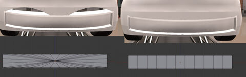
Left: A 'starburst' UV mesh with an unwanted wavy cutout. Right: The same fixture, but with a different UV mesh flow and no cutout problems.
Creating a Conforming Mesh
A conforming mesh is a single basic polygonal mesh that conforms to the shape of the car body.
The conforming mesh should have enough polygons at regular intervals so that it doesn't appear blocky or clip through the car body. The more polygons you add to the conforming mesh, the longer it will take to calculate its final morph position, but this does not impact performance when it is dragged around.
For this example fixture, we'll be using a conforming mesh for two purposes:
- Connecting the skinned mesh to the car body.
- Covering the cutout hole created by the UV mesh.
However, a conforming mesh can be used without a skinned mesh, such as:
- for trim pieces, bonnet bulges, or badges.
- for vents and grilles, when used with a UV mesh.
We'll start by using the UV mesh as our reference point. Our conforming mesh needs to cover the hole created here, so we'll make a ring of faces to surround the UV mesh with enough width to not allow any visible gaps between the cutout and the conforming mesh. We'll extend this edge out along the -Y axis (forward from the car body) by a millimetre or two to prevent faces from clipping through the car body, and we'll extrude a ring of faces around the outside of it to connect the mesh to the car body like so:

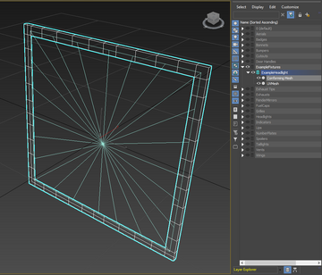
A conforming mesh covering the outside edges of a UV mesh, extruded out in to the -Y axis slightly to avoid clipping through the car body, and with a ring of faces around the outside to avoid it looking like it's floating.
Because this fixture is going to have a skinned mesh, we'll need to take that into consideration too. A skinned mesh will have any vertices that are farther than 1.5 mm in the -Y axis conform to the car in the same way as a conforming mesh, so we'll need to match this mesh structure such that the two meshes connect seamlessly. Here is the conforming mesh, with the skinned mesh and UV mesh:

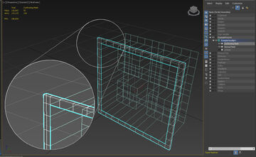
Note that the innermost edge of the conforming mesh lines up perfectly with the outermost edge of the skinned mesh.
This headlight fixture will also have a glass cover over it, so we'll add that in now. For this example, I've added a small step to the inside of the conforming mesh to add a little bit of detail. The glass cover will then be placed on top. You'll also notice that the outside edge of this headlight has been extruded deep behind the surface; this is so it can be placed on top of other headlights or grilles and not appear to float.

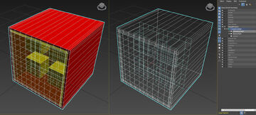
Left: Face view of the conforming mesh. Right: Wireframe view.
Unwrapping the Mesh
The next step is to unwrap the mesh. We'll be using 3ds Max's default UVW Map modifier, setting it to 'box' projection (cube projection in Blender), and setting the length, width, and height dimensions all to 2. This value is important if your fixture mod intends to use our default materials, because said materials assume that the UVs of the fixture conform to this setting.
Basically, what this is doing is UV mapping the mesh so that the 0-1 areas of the UV map are 2cm².

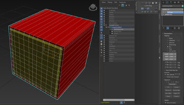
The finished conforming mesh with a UVW Map modifier set to a 2, 2, 2 box projection.
We'll go over the import process and material setup after we've created all of the meshes.
Creating a Skinned Mesh
A skinned mesh is the most complicated mesh in a fixture. It follows the same rules as the conforming Mesh in terms of overall mesh structure and UV mapping, but the manner in which it conforms to the car is more nuanced.
The vertices of a skinned Mesh will conform to the car in the same manner as the conforming mesh if those vertices are within 1.5 mm of the Y axis. This is useful for having these parts of the mesh connect to a conforming mesh, as they will conform the same in that area.

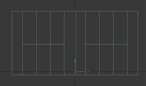
Note that only the vertices on the lowermost edge of this mesh will conform as if they were part of a conforming mesh, as the rest are farther than 1.5 mm from the body surface. Also note that these vertices will maintain this offset from the Y axis even after they have conformed to the car; thus, the conforming mesh will need to extend at least as far to connect to these vertices.
The rest of the mesh will conform relative to their skinned bones and weights. For this example, I've created a Skinned Mesh with 4 bones, and weighted them like so:

Each bone is weighted to the parts of the skinned mesh that should retain their proportions, with the intermediary vertices weighted smoothly between bones.

The bones in motion.
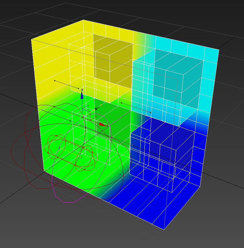

The bones are free floating, and are parented only to the bone root. I usually use Dummy Actors for my bones, but you can use a box mesh or whatever works.
Take note that the vertices that conform to the mesh do so in the same manner as the conforming mesh, but are still weighted to their respective bones. This is because Automation's fixture system uses the distance that these vertices were morphed to determine how far back to conform each bone. If these vertices were weighted to the root bone instead, the fixture would not know how far to morph the skinned sections of the mesh.
Unreal Engine 4 also requires a bone hierarchy, so I've made a root bone and parented all of the other bones to it. The root bone should not be weighted to any vertices.
From a front view, you can see that the bones are centred on their respective elements.
Top view.


Take a look at the image below of the skinned mesh on the car (there's also a conforming mesh there around the edge, but we'll ignore that for now). The outer ring of vertices is conforming to the car as if it was part of a conforming mesh, and the rest of the mesh is conforming as per their bone weights:

Unwrapping the Mesh
Assign the same box map (with a scale of 2, 2, 2) as you did with the conforming mesh.
Creating an Additional Mesh
An Additional Mesh is a simple mesh with no skin or morphs that does not deform in any way. The Additional Mesh does rotate around the fixture position, and will maintain its relative position from its pivot point.
Take the following example: an exhaust fixture. Note that the entirety of the exhaust is offset from the pivot point—this is so that it can hang under the car, since the fixture itself must have its pivot point on the car.
3D view.
Front view.


Additional Considerations
Unwrapping reflector lights
If your fixture is a light that contains a reflector surface (such as an incandescent bulb), there are some special considerations.
Let's take a look at this fixture as an example:

Several things are of note with regards to light components:
- The bulbs themselves should be unwrapped as a single point with zero scale exactly at UV coordinate
0.5,0.5(the UV is scaled to a single point in the very center). - The main reflector surface should be unwrapped such that each quad face fills the entirety of the
0-1UV coordinate space (Reset UV projectionin Blender). - The side walls of the reflector (and any other part of the reflector that you want to have vertical or horizontal lines on) should be unwrapped as a single point with zero scale exactly at UV coordinate
0,1(the UV is scaled to a single point in the bottom left corner). - Parts of the reflector that should appear flat should be unwrapped as a single point with zero scale exactly at UV coordinate
0,0(the UV is scaled to a single point in the top left corner).
Applying materials to a light component
The bulb and reflector for each light should be assigned to the same material slot to save on draw calls. Each separate light, however, should be a different material slot for freedom of choice in terms of light configurations.
Unwrapping radial glass
For light glass with a radial pattern, unwrap the glass so that the radial pattern fills the whole UV space as a single texture.
Fixture setup within Unreal Engine 4
This step assumes that the correct version of Unreal Engine is installed and configured correctly. See Modding for more information on the correct version of Unreal Engine to use and how to view mod content folders. Also see the official Unreal Engine documentation on importing FBX files for more information.
Creating your Fixture Mod Plugin
Using the correct version of Unreal Engine, with our modding tool project opened and plugins loaded, select 'Create Mod' from the top menu bar.
1) Select the blank project. 2) Give your mod a unique name. 3) Fill out your name and a description of this mod. 4) Create the mod.
Importing Files
There are several ways to import your sub-meshes to this mod folder. The easiest is to simply navigate to the folder you want to import your files in the Content Browser, then click the 'Import' button to import files to that folder, select the meshes you want to import, and click 'Open'.

UV meshes, conforming meshes, and additional meshes should be imported as static meshes ('Skeletal Mesh' is un-ticked in the import dialogue), while skinned meshes should be imported as skeletal meshes ('Skeletal Mesh' is ticked in the import dialogue).
Note that 'Skeletal Meshes' will import with additional 'Skeleton' and 'Physics Asset' files. These are important. You don't need to do anything with them, but don't delete them.


An example import dialogue for a skinned mesh. This should be unticked for other sub-mesh types.
Note that 'Import Materials' is also unticked, as we do not want to import any materials from the modelling software. The final set of imported files in Unreal Engine should look like this:

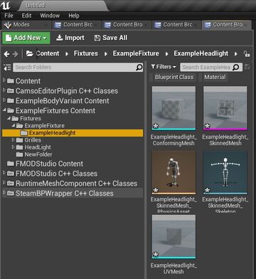
Note that this example does not include an additional mesh.
Once your files are imported, it's important to set 'CPU Access' to true for all static meshes. You can do this by selecting every static mesh, right-clicking on it and selecting 'Set Meshes to Allow CPU Access'.

Default Materials and Material Slots
Note: This step assumes a basic understanding of UE4's Static Mesh editor and Skeletal Mesh editor. Alternatively, material slots can be named appropriately within a 3D modelling program of choice.
The fixture material system in Automation relies on the name of the material slots within the meshes to define what materials can be applied to the fixture. Therefore, assigning the correct materials to the meshes is only important for the initial selection and loading of that fixture. In this manner, it is possible to have custom materials applied to your fixture with it still being compatible with Automation's fixture material menu.
The fixture material menu in Automation relies on the names of the material slots on the sub-meshes to decide what category of materials the player can select from, with said names in the format category_# (case-sensitive, with '#' being a single- or multiple-digit number of choice).
The available categories for fixture materials are as follows:
panel(car body colours and some other opaque materials)opaqueglass(opaque light glass; ideal for non-bulb lights)grill(for transparent and opaque grill patterns in addition topanelmaterials)glass(transparent and translucent light glass in addition toopaqueglass,panel, andgrillmaterials; this category provides the most freedom in terms of material choice)roundglass(transparent light glass with radial detailing; this material applies to a mesh in the traditional UV sense, so use a planar map to unwrap this part of the mesh if you intend to use this)bulb(for reflector lights; requires special UV unwrapping)numberplatenarrow(North American license plate format)numberplatewide(European license plate format)

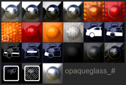

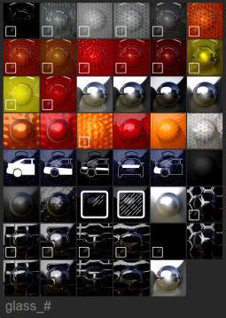

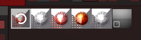

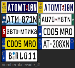
If you only have a single slot for a fixture material category, you still need a number for it. This number scales infinitely, meaning a fixture can have many separate slots of a single category assigned to it. A fixture's sub-meshes cannot share the same name on its material slots. If a fixture contains meshes with duplicate slot names, they will appear as a single material slot in-game (this can be used to merge slots on, for example, a conforming and additional mesh).
With light fixtures, the names of the slots for the corresponding pair of glass and reflector material slot names should share the same number. For example, a fixture with two lights would have glass_01 (or just glass_1) and bulb_01, and glass_02 and bulb_02.
Below is a headlight's conforming mesh with its default materials set and the names of its material slots set to their respective types. The workflow for additional meshes should be identical.
Close-up view of the materials
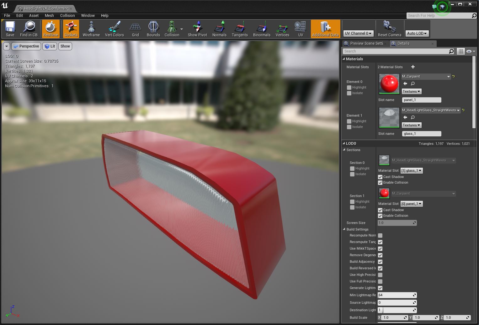
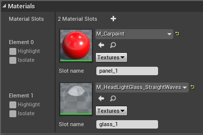
The Skeletal Mesh editor looks a little different, but the slot naming conventions are the same:

Assigning Default Materials
While the slot names define what materials the player can choose from in-game, it doesn't define what material first gets loaded when the fixture is spawned in.
When the fixture is first placed on the car, it loads the material that is set in that fixture's sub-mesh default materials. For the sub-mesh examples above, you can see that not only have the slots been named appropriately, they also have materials assigned to them. Therefore, for all your fixture sub-meshes, default materials should be applied. (They're not strictly necessary, but your fixtures deserve better than the default grey checkered material.)
To find where all the materials available in-game are, open up the CarMaterialUtils blueprint (located in Content -> Utility), and open the 'Get Materials from Slot' function. There, you can view the list of each material that gets assigned to each slot, find them in the content folder, and assign them to your mesh as the default material. Note, though, that these steps are only to find where the default materials are. We do not use the Utils blueprint itself to assign materials to fixtures.
To do this, open CarMaterialUtils...

...then open 'Get Fixture Materials from Slot', located in CarMaterialUtils -> Car Painting -> GetFixtureMaterialsFromSlot.
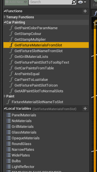
From there, select the corresponding materials array for the material category you want to apply to your sub-mesh from the Local Variables tab, and in the details panel you'll see an array of the materials used for that slot type. By expanding that, you can see the materials, and by selecting the small magnifying glass icon, view that material in the Content Browser, and from there apply it to your sub-mesh.
Creating and Setting Up the CPP File
Right-click in the content browser, and from the 'Camso' sub-menu, select the 'Fixture Preview Data' option. You should now have a fixture CPP file in your content browser.

Open the CPP file. You should get something like this:

Fill out the 'Meshes' section with the meshes you've made, leave the 'Text' data empty, generate a GUID and Family GUID (or copy the family GUID if you're making a variant), and set the 'Fixture' settings to the relevant info as laid out near the top of this page. Finally, in the 'Path' section, make sure there is one item in the array, and fill it with A_Fixture. This is important; your fixture will not work if this is not filled correctly.
When you're done, you should have something that looks like this:

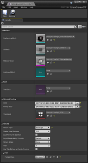
A fixture blueprint with only the relevant settings shown.
Be sure to save your files.
Creating the Thumbnail
You should already be here by default when you load up the Automation project. Check the top tab in Unreal and make sure it says 'ThumbnailGeneratorLevel_Fixture'. If you are not in the thumbnail generator level, open it from DeveloperSandbox/ThumbnailGeneratorLevel_Fixture.


From the top menu, open the drop-down next to the 'Play' button and select 'Simulate'. You should now be 'simulating' the level.

Generate Fixture Thumbnails
Select the Fixture Thumbnail Generator from the World Outliner, and add your fixture blueprint to the 'Fixture Previews to Generate' array (by first clicking the 'plus' icon, then putting the fixtures you have created into the list). Repeat this process for every fixture you have created. It does not matter if these fixtures are of the same family or not. Then, select 'Export Preview' to generate the Thumbnail file.


Note that I am connected to source control in this .gif, which explains the red checkmarks in the top right corner of the items in the Content Browser. If you do not see this, do not worry.
Because these files are created by the modding tools, they need to be manually saved (even if no asterisks are present).
Your fixture mod is now ready to be shared!
Cooking and sharing your mod
To use the mod you have just created, you need to 'share' it. See the main Modding page on how to share your mod.
Additional notes
- Fixtures should not have any vertices along the centre axes to avoid any miscalculation by the fixture gizmo. If the game casts a ray through the centre line of the car, it may miss the two halves of the car and return a false positive of the fixture being out of bounds. Offsetting your vertices slightly will avoid this. Additional meshes are the sole exception to this rule, as they do not conform in any way.
- If you're testing out a fixture and the meshes it uses haven't been finalized, you can use UE4's 'Reimport' function to replace the existing mesh with a newer version of it. All the materials already assigned to the mesh will be preserved, as will its reference in the blueprint, saving you the trouble of manually reimporting a mesh and having to reassign materials and put it into the blueprint again. This works for car body meshes as well.
- Is CPU access still turned on for all static meshes? If your mod causes a crash or isn't visible in-game, this might be unticked. It does that sometimes; re-enable it and try again.
- If the first fixture in a thumbnail generation array ends up with an unusually sparkly thumbnail, this can be fixed by giving it an additional duplicate array entry (which forces UE4 to render the thumbnail again normally).